Project
Development of an over terrain vehicle (OTV)
ByAkash Bhave
Published on Monday, November 29, 2021

The process of building our over-terrain vehicle (OTV) for the ENES100 first-year engineering keystone course involved lots of rapid prototyping. This is a summary of the numerous prototyping iterations we went through for the various components of the OTV.
Chassis
Having a base for our OTV was essential to further development at the beginning of the semester. To start off, we found a large piece of scrap plywood next to the laser cutter. This piece of wood happened to be large enough to accommodate our entire build. The thickness (1/8") and weight were also ideal. We quickly completed the necessary training for the band saw and cut the piece of wood to our specifications. Originally, we planned for this to only be the prototype chassis; however, the material proved to be sufficient for our final design.
Locomotion
To minimize costs, we choose to 3D-print all custom components in our locomotion system. This included the motor mounts, motor shafts, and spacers. Initially, the parts would work perfectly. Unfortunately, over time, the screw holes that held the wheel to the motor dilated. This greatly reduced the performance of the motor and led to the wheel falling off while it was moving. We re-printed the same parts multiple times to confirm that this issue was inherent in the material. Our final design replaces the 3D-printed PLA parts with stainless steel parts ordered from Pololu.
Sensing
Angled approach
While brainstorming at the beginning of the semester, we thought of a sensor "hut" that included one ultrasonic sensor facing forward and an additional ultrasonic sensor angled upwards to capture the height of the wreckage face. During an earlier design review, we realized that the angled sensor would not receive readings as the sound waves would bounce upwards.
Straight approach
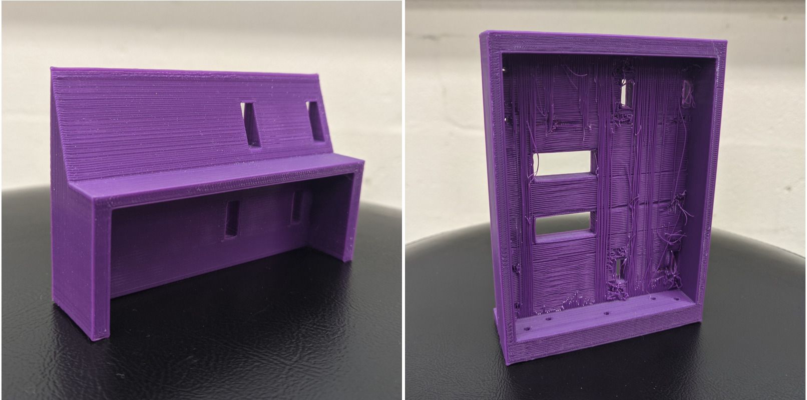
Next, we removed the angle on the top ultrasonic sensor, instead elongating the hut so that the top sensor would be level with the wreckage face in its tallest orientation. However, we realized that the tall hut would collide with the bottom of the limbo. Additionally, because our motors were specifically selected to operate at a lower power, we were unable to update the design to traverse the log.
Algorithmic approach
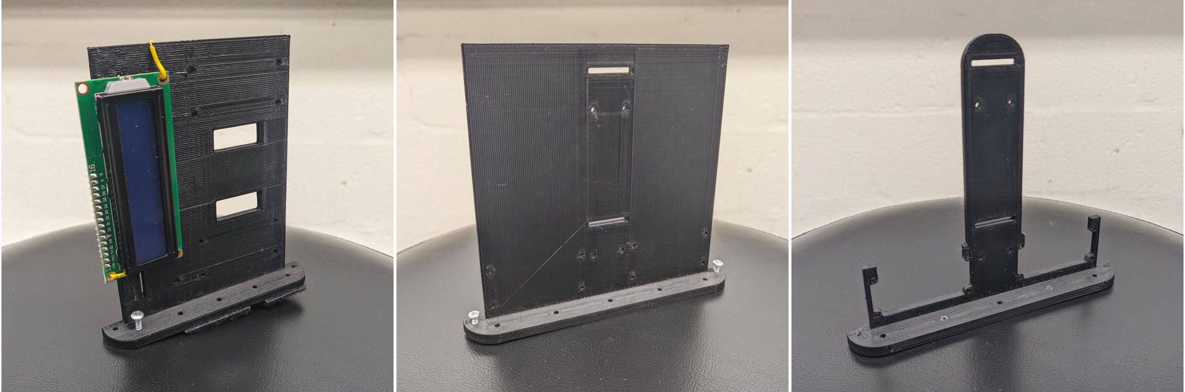
After a particularly focused meeting, we collectively concluded that we didn't actually need to measure the height of the wreckage. We know each of the wreckage orientations are unique; thus, if we knew the length and width of the face touching the ground, we could derive the height.
This realization eliminated the need for an elongated hut, so we were once again cleared to go under the limbo. Our initial design had the two ultrasonic sensors in the horizontal orientation, which ended up reading the edges of the wheels. We updated the design with the ultrasonic sensors rotated vertically. This design still read the edges of the wheel, so we elevated the design by one inch with a small wood piece.
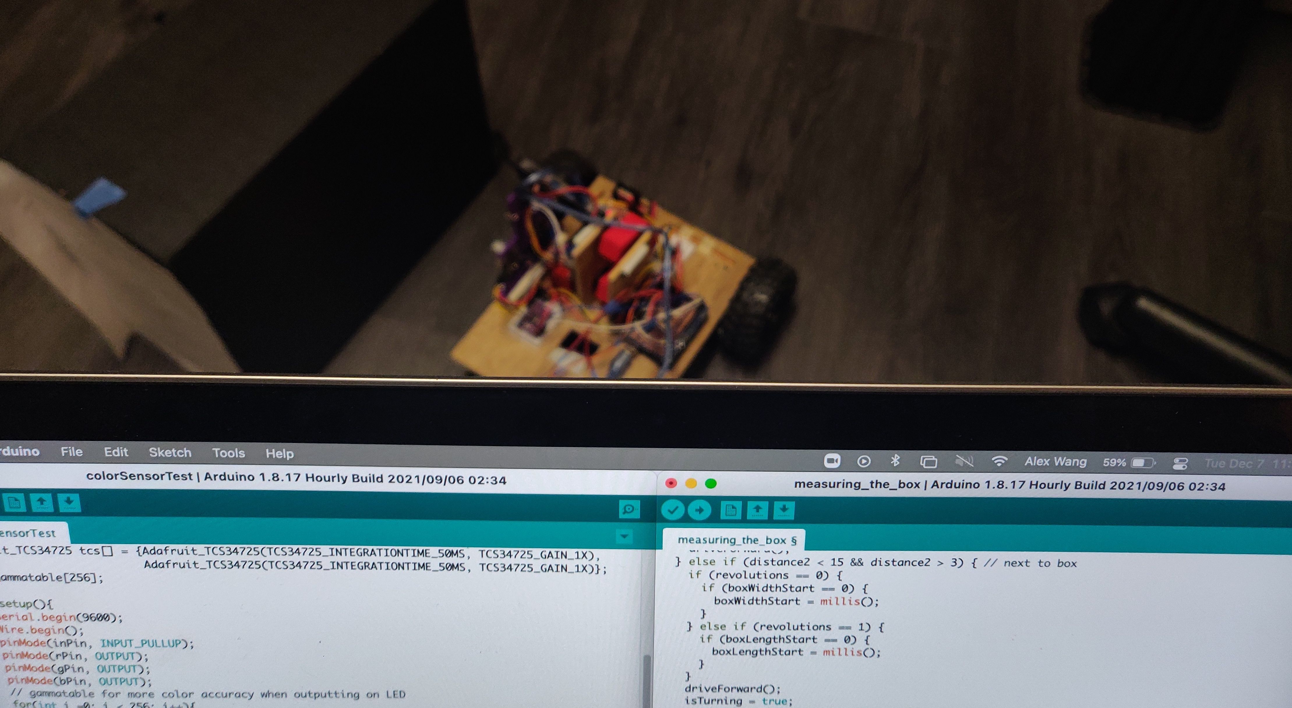
Electronics
As soon as we knew what parts we needed for locomotion and sensing, we drafted an electronics schematic diagram. Luckily, this original draft was fairly similar to what the final draft looked like, which is pictured above. Between the first and last drafts, we removed a few extra ultrasonic sensors, added two color sensors and an I2C multiplexer, and optimized the number of digital pins being used on the Arduino.