Project
Proposal for a neuromorphic neural network
ByAkash Bhave
Published on Friday, October 16, 2020

Background
The neural network (NN) is an increasingly popular type of computing in today’s world of machine learning. For the most part, neural networks are currently implemented in computer programming languages, like Python and JavaScript. NNs designed using a software-based approach are easy to prototype, but have limitations regarding power consumption and performance.
Neural networks
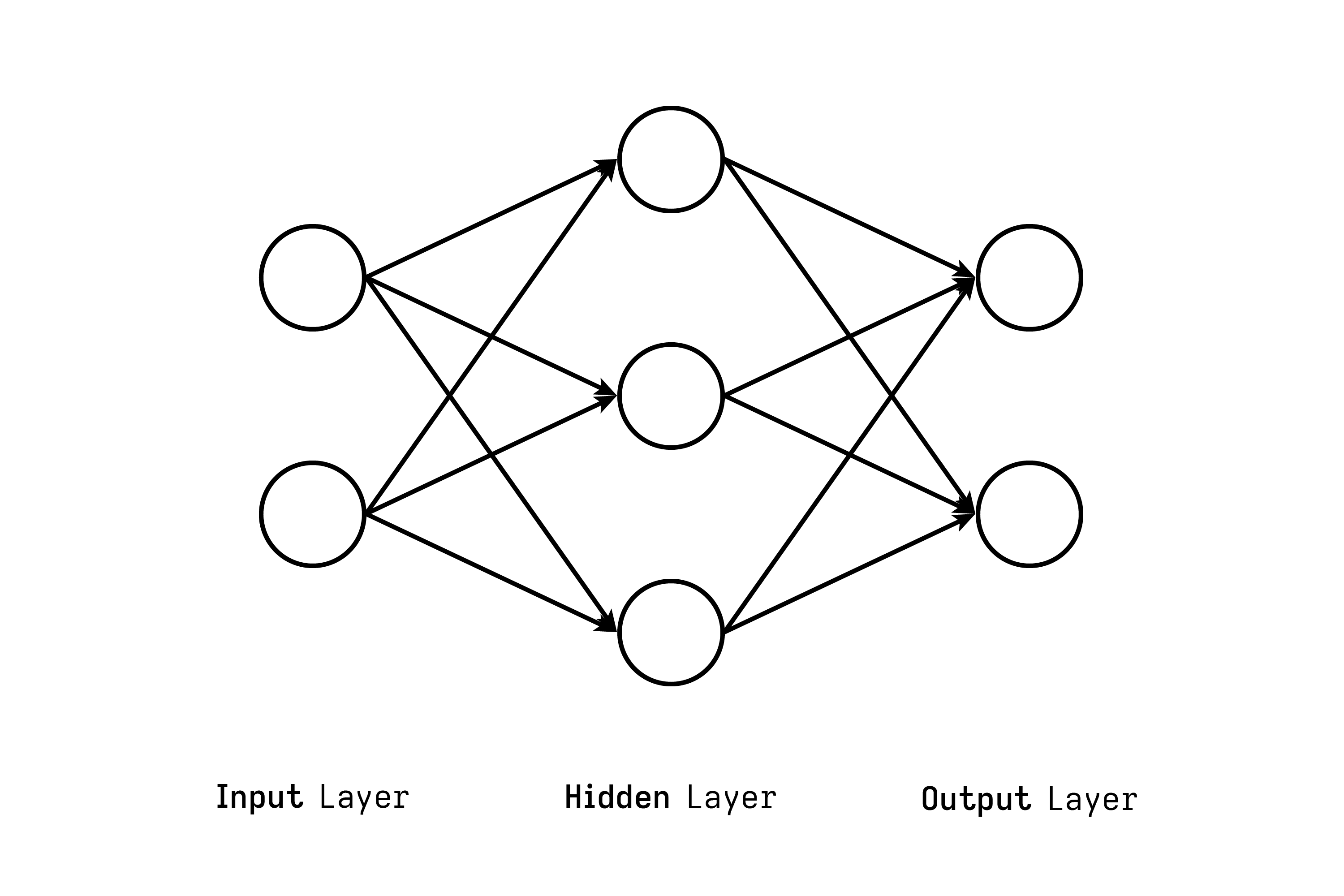
Most simply, a neural network is a series of algorithms that recognizes relationships between data. They are “neural” in that they somewhat mimic the way the mammalian brain operates. The neural network that I will focus on in my project is the simplest type of NN: the artificial neural network (ANN).
The most basic unit of a NN is the perceptron or node. A perceptron’s job is to take in a vector (or 1-D matrix) of inputs, sum the values, and then apply an activation function to the sum. Perceptrons arranged in a column constitute a layer. Perceptrons are connected between layers with weights. When a perceptron “passes” a value to the next layer’s perceptron, the value gets multiplied by the weight that connects the two perceptrons. Thus, the operations between two layers can be represented by a multiplication operation of two matrices. Finally, an activation function (commonly the sigmoid function or the hyperbolic tangent function) is applied to the sum of all these weighted values.
There are two primary algorithms involved in neural networks. The first algorithm is the feed-forward process that occurs as follows: (1) input values are received on the left side of the network, (2) matrix operations occur as data flows right, (3) and output values are produced on the right side of the network.
The second algorithm involved in a neural network is the backpropagation algorithm, which calculates the error in the network’s output values and adjusts the weights accordingly. This is carried out using both matrix multiplication and multivariable calculus. My project will assume that the weights in the network have already been tuned beforehand, and therefore will only perform the feed-forward process.
Neuromorphic systems
Recently, there have been significant developments in the world of neuromorphic computing—an approach to computing that is inspired by the activity of the biological human brain. Because neuromorphic systems exist much lower on the hardware stack when compared to software-based systems, they are able to operate more efficiently. However, implementing such neuromorphic systems is not straightforward.
At the moment, lots of research is underway on the chemistry front to develop neuromorphic electrical components. For neural networks, the memristor is the most promising innovation. It is a two-terminal device that relates magnetic flux and electric charge. Numerous neural network architectures have been proposed that utilize the memristor. Unfortunately, a working, physical memristor is under active development and is extremely hard to acquire. For this reason, my network will not use an actual memristor; rather, I will design a system using readily available electronic components that somewhat mimics the function of a memristor.
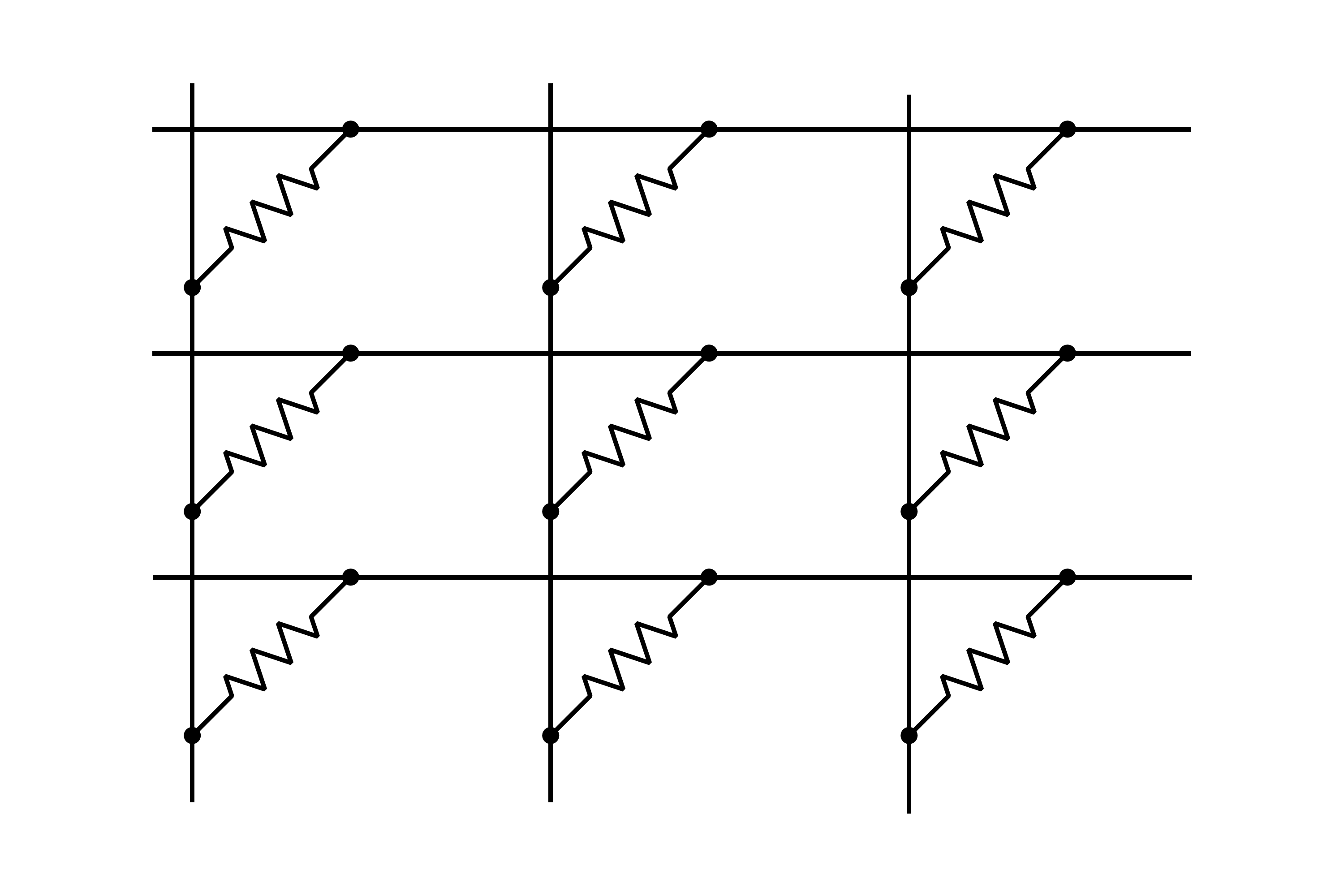
At the heart of my project is the crossbar array. This structure is what adds the term “neuromorphic” to my project’s title. The function of the crossbar array is to perform the matrix multiplication operation between network layers using analog techniques as opposed to digital ones. Basically, the output vector from one layer will feed into the top of the structure as voltages. The weight matrix will be encoded as resistances in voltage controlled resistors that connect wires in the array. Op-amps will be placed at the bottom of the structure and will output voltages proportional to the sum of the currents flowing through the resistors.
Application & significance
Neuromorphic systems have great significance in low-power, embedded environments due to their efficient runtime and close proximity to hardware. Such systems could be used in defense and Internet-of-Things (IoT) applications.
There are a few examples of neuromorphic systems that are currently being used for real-world applications. The IBM TrueNorth chip (a manycore neuromorphic network) is already being used by DARPA on the SyNAPSE board. Intel’s Loihi chip, a self-learning neuromorphic computing system with impressive power efficiency, is being used in medical and environmental applications.
Objectives
To test the success of my project, I will have my neuromorphic neural network compute the cosine of a given number. The reason for choosing such a trivial task is that the network architecture will be extremely simple—it can be as easy as one input perceptron, two hidden layers with three perceptrons each, and one output perceptron. Additionally, training the network through computer programming will be straightforward. Although the criteria is simple, having my project successfully complete this task will indicate that the crossbar array is effective and that the analog-digital-analog conversions are functional.
Approach
Below is an overview of the steps that I will take to design and implement my project.
- Design a general block diagram for my project.
- Create a schematic for the crossbar array, especially taking into account the operating ranges of each of the electrical components. These operating ranges will determine the valid input and output values of the network.
- Simulate the crossbar array using LTspice.
- Design schematics for the ADCs and DACs that will interface between the FPGA and the crossbar array.
- Write the gate connections for the FPGA that will output values to the DAC, wait until the crossbar array completes its calculations, read the values from the ADC, then repeat with the next layer.
- Attempt to simulate the FPGA’s functionality with digital simulation software (details are unknown here).
- Perform the final cosine test by connecting all the subsystems together.
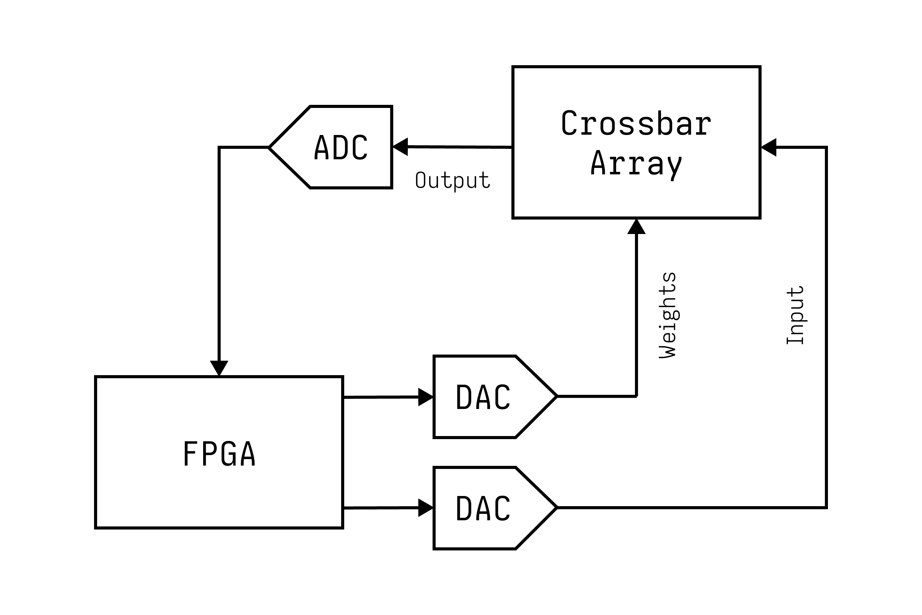
Original block diagram for my proposed implementation.
Timeline
- 2020-10-31: Develop schematic of the crossbar array. Determine which analog components I need to request from the lab.
- 2020-11-31: Simulate the crossbar array in LTspice. Confirm that the components I requested will work in a physical implementation.
- 2021-01-31: Wire and test a physical implementation of the crossbar array. This requires that I have all the necessary electronics tools, such as a power supply and an oscilloscope.
- 2021-02-31: Develop schematics of the FPGA and AD/DA converter systems.
- 2020-03-31: Program, wire, and test the FPGA and AD/DA converter systems.
- 2020-04-31: Connect all subsystems of the project together. Judge the network’s success using the aforementioned cosine test.
Materials & funding
- TinyFPGA BX (provided by me, $38): The primary digital component of my project.
- Oscilloscope (provided by me, approx. $80): Used for measuring voltages in the crossbar array as well as testing the function of the DAC.
- Power supply (provided by me, approx. $50): Supplies power to the components in the crossbar array.
- ADCs and DACs (provided by the lab): Used to interface between the crossbar array and the FPGA. The lab should already have some of these components. The exact models of these components are unknown at this time.
- Various discrete components (provided by the lab): This includes op-amps, JFETs, capacitors, and resistors. The exact components that I will need are unknown at this time.